Zero-Copy Pipelines

In the high-stakes world of embedded systems, there is often a vast, perilous chasm between a system that "functions" and one that performs. A prototype might capture an image, but if that simple act paralyzes the entire device for 200 milliseconds blocking network keep-alives, delaying sensor readings, and freezing the user interface—is it truly a viable product?
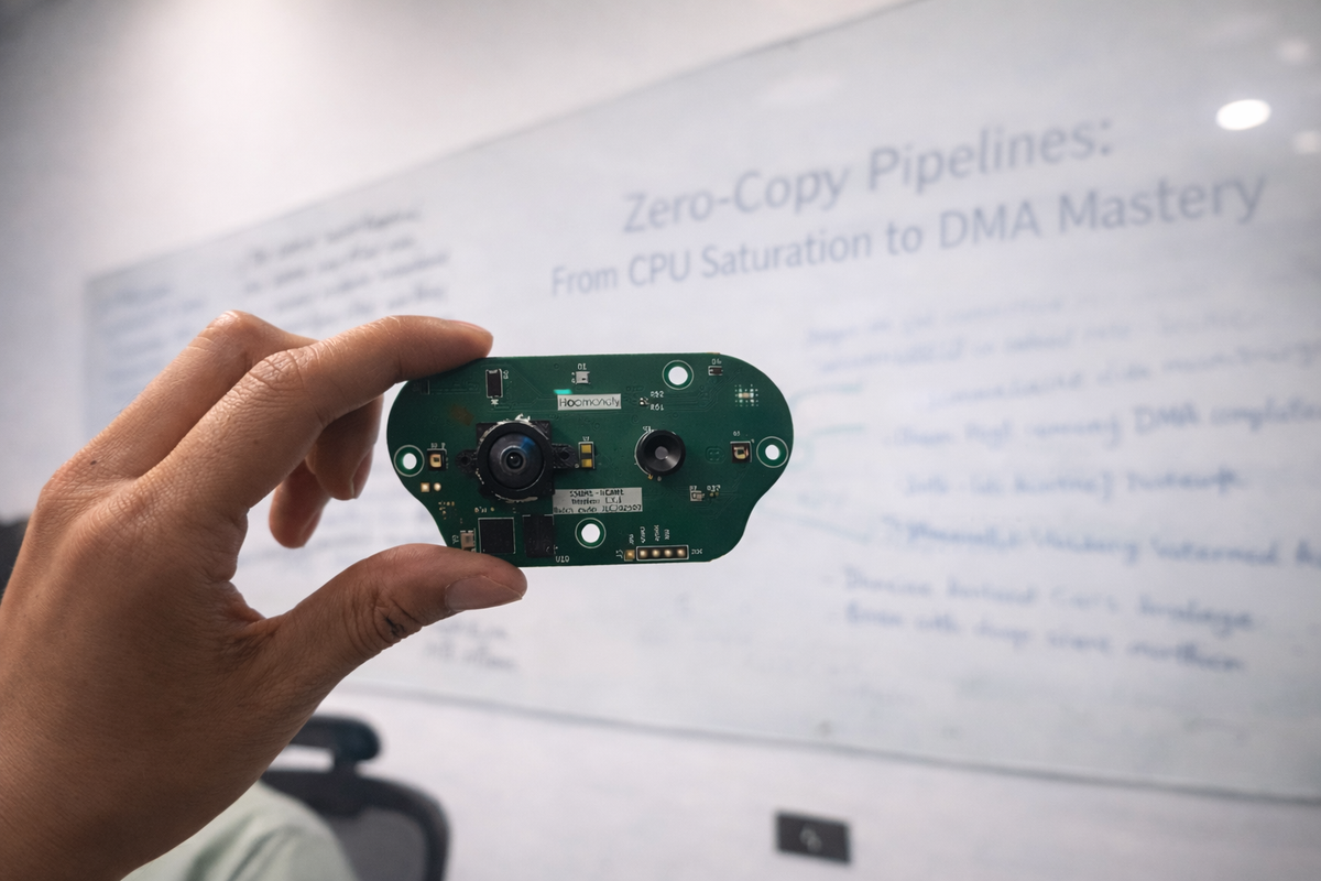
When our team embarked on the firmware development for our high-performance STM32H5-based imaging system, we faced exactly this dilemma. Our mandate was deceptively straightforward: capture high-resolution (1MP) monochrome images from an AR0144 Global Shutter sensor and stream them to massive external storage. It sounds like a standard requirement for a modern Microcontroller Unit (MCU). We had the hardware capabilities on paper—a powerful 250MHz Cortex-M33 core, a dedicated Digital Camera Interface (DCMI), and the newly introduced GPDMA (General Purpose DMA) controller.
However, as we started implementing the initial pipeline, we quickly discovered that datasheet specifications are optimistic, and real-world silicon is unforgiving. What should have been a simple data transfer turned into a weeks-long battle against bus contention, cache coherency "ghosts," and CPU saturation.
This article details the technical odyssey of how we moved from a stuttering, blocking implementation to a fluid "Zero-Copy" pipeline. We will discuss the architectures we rejected, the specific debugging techniques that revealed the invisible wars fighting inside the memory bus, and the final solution that allowed us to process megabytes of data without the CPU ever engaging its Arithmetic Logic Unit (ALU).
1. The Challenge: When Math Meets Reality
To understand the magnitude of the problem, we first have to look at the numbers.
Our Camera sensor outputs a 1280x800 pixel image. At 8-bit monochrome depth, that is roughly 1.02 MB of raw data per frame. The STM32H5, while a beast of a microcontroller, has a fragmented internal SRAM architecture. It does not have a single contiguous block of RAM large enough to hold a full 1MB frame while also reserving space for the RTOS stacks, heaps, and application variables.
This physical constraint dictated our system architecture: we had to rely on external memory. We chose an PSRAM (Pseudo-Static RAM) connected via the high-speed OctoSPI interface. This memory is fast, cost-effective, and offers plenty of space. The theoretical plan was simple:
- The DCMI peripheral receives pixel data from the camera.
- It buffers it temporarily.
- We move it to the large external PSRAM.
The Bottleneck: Bus Contention
Our first implementation followed the standard "textbook" approach for embedded drivers. We set up the DCMI to trigger an interrupt when it had filled a small buffer in internal RAM. Inside that interrupt, the CPU would copy that chunk of data to the external PSRAM.
It failed immediately and spectacularly.
The images we captured were "torn." The top 20% of the image would be perfect, but the rest would be a jumbled mess—shifted horizontally, corrupt, or missing entirely.
The root cause was Bus Contention on the AHB Matrix. The STM32H5 uses a multi-layer bus matrix to arbitration access between masters (like the CPU and DMA) and slaves (like memories and peripherals).
- The Aggressor: The DCMI peripheral. It has a very small internal FIFO (First-In-First-Out) buffer. Pixel data pours into this FIFO at the relentless speed of the hardware pixel clock. If you don't drain it instantly, it overflows.
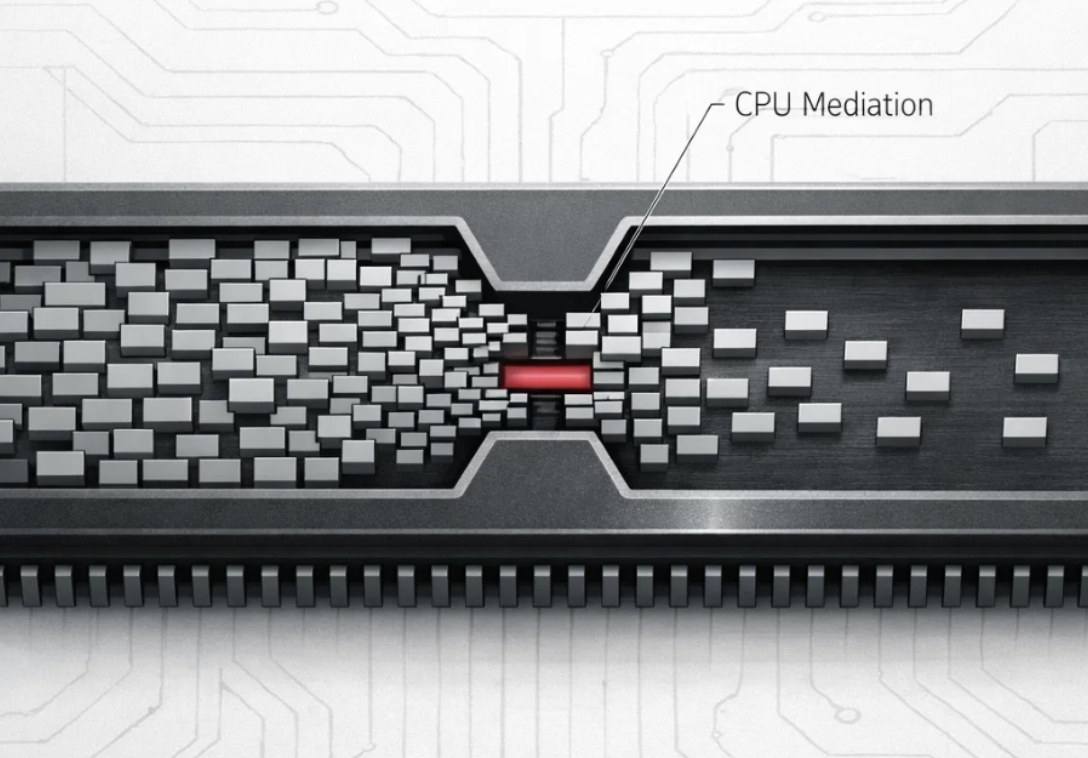
- The Victim: The CPU. To move data to external PSRAM, the CPU has to fetch instructions from Flash, read data from SRAM, and write data to the OctoSPI peripheral.
In our "User-Copy" implementation, the CPU was trying to saturate the bus to write to the external memory. Simultaneously, the DCMI was screaming for bus access to write its incoming pixels to internal RAM. In this high-speed tug-of-war, the DCMI often lost. The FIFO overflowed, pixels were dropped, and the synchronization of the image was lost forever.
We realized that at these data rates, the CPU is not just a bottleneck; it is a liability. As long as the main core was involved in moving bulk data, the system would never be robust.
2. The Alternative Paths Not Taken
Before we committed to re-architecting the entire system, we performed a rigorous trade-off analysis of alternative solutions. It is important to note that "Zero-Copy" is not the only way to solve this, but for our specific constraints, it was the optimal way.
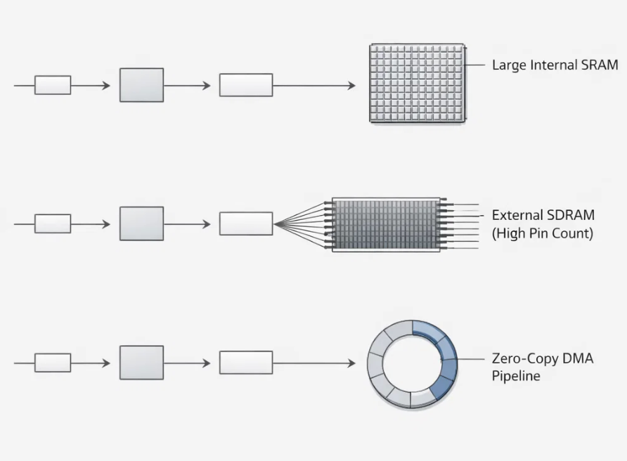
Option A: The "Big Internal RAM" Approach
The simplest engineering solution would have been to upgrade to an MCU with 2KB+ of internal SRAM.
- The Logic: If we had enough internal RAM, we could capture the entire frame in one go without touching the external bus, effectively decoupling the capture from the storage.
- The Dealbreaker: Cost and Footprint. MCUs with that much internal SRAM are significantly more expensive and often come in larger BGA packages that wouldn't fit our compact PCB design. We were committed to the STM32H5.
Option B: External SDRAM with Dedicated FMC
Many high-end Data Loggers use an external SDRAM chip driven by a dedicated FMC (Flexible Memory Controller).
- The Logic: The FMC is a dedicated hard-block that handles memory refresh cycles and burst writes extremely efficiently, often yielding higher sustained throughput than OctoSPI.
- The Dealbreaker: Pin Count. A typical 16-bit SDRAM interface requires 30-50 GPIO pins. Our microcontroller package was pin-constrained. Devoting 40 pins just to memory would have left us with no I/O for our thermal sensors, radios, or user buttons.
Option C: The Compressed Stream
We briefly considered compressing the image line-by-line (e.g., using a lightweight RLE or JPEG algorithm) as it came in, reducing the data volume before writing to memory.
- The Logic: If you reduce the data by 50%, you reduce the bus pressure by 50%.
- The Dealbreaker: Computational Cost. The AR0144 is a raw sensor. Doing software compression at line-rate would burn even more CPU cycles than the simple copy operation, likely exacerbating the tearing issue rather than solving it.
We were cornered. We had to make our specific hardware configuration—DCMI, OctoSPI PSRAM, and a busy CPU—work in harmony. The only way forward was to optimize the pipeline itself.
3. The Journey: Fighting the "Ghosts" in the Machine
We made the decision to implement a Direct Memory Access (DMA) pipeline. We configured the STM32's GPDMA controller to move data directly from the DCMI peripheral to the external PSRAM, bypassing the internal SRAM copy entirely.
We set up the descriptors, fired the trigger, and dumped the memory. The transfer "worked." The correct number of bytes were written to the address. But when we visualized the data, it wasn't an image. It was garbage.
The Detective Work: Anatomy of a Glitch
This wasn't random noise. It was a precise, repeating pattern of corruption. We spent days with logic analyzers and hex dumps, staring at the raw memory view. We noticed a peculiar phenomenon:
- We would see 32 bytes of perfect pixel data.
- Then we would see 32 bytes of zeros.
- Then 32 bytes of perfect data.
- Then 32 bytes of zeros.
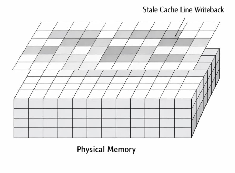
It looked like someone had overlaid a barcode on our photo. This specific number—32 bytes—rang a bell. It is the exact size of a Cache Line on the Cortex-M33.
The Villain: D-Cache Incoherency
We had stumbled into one of the most classic, yet frustrating, traps in embedded systems: Cache Coherency. The Cortex-M33 employs a Data Cache (D-Cache) to speed up memory access. When the CPU reads from a memory address, it loads that data (and its neighbors) into its high-speed internal cache.
Here was the invisible sequence of doom:
- Initialization: At startup, the CPU clears the frame buffer in PSRAM to zeros. The CPU's cache now "remembers" that those addresses contain zeros.
- The DMA Write: The DMA (which is a separate bus master) writes the beautiful new image data directly to the PSRAM physical memory. Crucially, the CPU does not see this happen.
- The Housekeeping: Later, the CPU decides to do some work. It looks at its cache, sees "dirty" lines (the zeros it touched earlier), and decides to flush them back to main memory to make space.
- The Overwrite: The CPU blindly writes those cached zeros over the new image data the DMA had just painstakingly written.
The DMA had done its job perfectly, but the CPU—working with "stale" information—unknowingly undid it. We were fighting a ghost. The CPU believed it was helping by saving its data, but it was actually destroying ours.
4. The Solution: Architecting the Zero-Copy Pipeline
To solve this, we couldn't just "patch" the code. We had to design a system that enforced data integrity by design. We called this the Zero-Copy Pipeline.
The philosophy was simple: Data ownership is passed, never copied.
Component 1: The Circular Linked-List DMA
We abandoned the idea of a linear buffer. Instead, we configured the PSRAM as a circular ring buffer (Ping-Pong-Pang). We utilized the STM32 GPDMA's powerful Linked List feature. In a typical DMA setup, you set a source and destination, and when the transfer finishes, it stops. You have to interrupt the CPU to set it up again. With a Linked List, we program the DMA with a set of self-referential instructions:
"Fill Buffer A. When done, automatically reconfigure yourself to fill Buffer B. When done with B, switch back to A."
This creates an infinite loop of capture capability. The DCMI can pour data forever without ever waiting for the software to "reload" the DMA. The hardware handles the wrapping logic instantly.
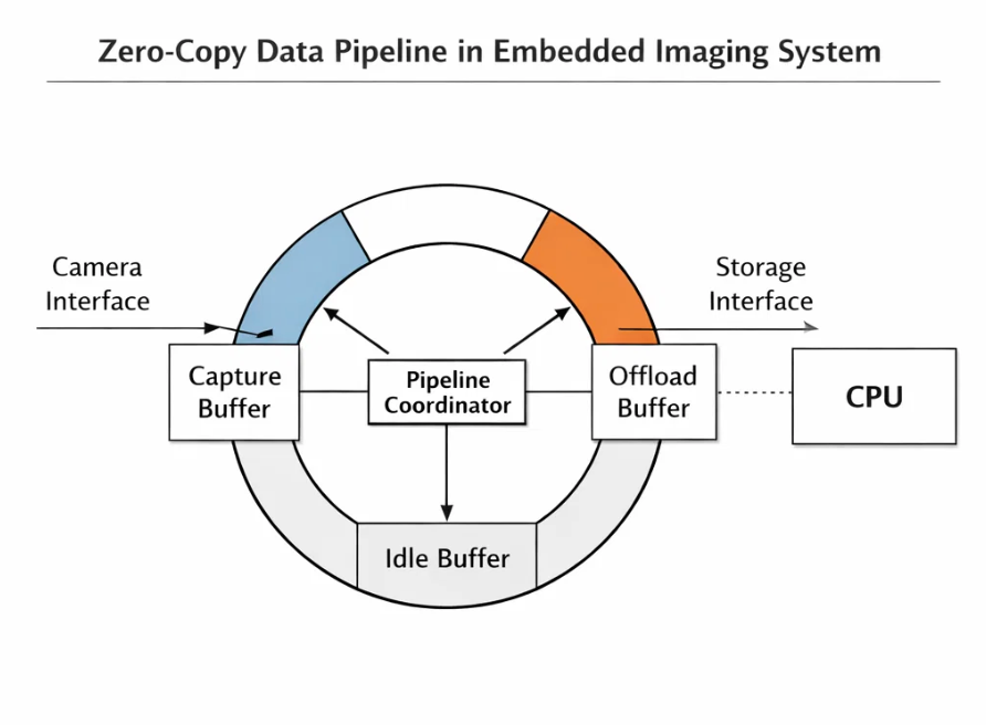
Component 2: The "Coordinator" State Machine
With the hardware running autonomously, we needed a "Traffic Cop" to prevent chaos. We built a software module called the Pipeline Coordinator. This module manages a strict state machine for every slot in the ring buffer:
- FREE: The slot is empty and available for the camera.
- CAPTURING: The DCMI is currently writing to this slot. (Locked)
- READY: The capture is complete, and the slot contains a valid frame.
- OFFLOADING: The storage thread is currently reading this slot to write to flash. (Locked)
The Coordinator enforces Strict Mutual Exclusion. The camera will never write to a slot marked OFFLOADING. The storage system will never read a slot marked CAPTURING. Crucially, the "handoff" between these states is just a pointer exchange. We pass the memory address 0x90000000 from the Capture Task to the Storage Task. We don't move the 1MB of data; we just move the 4-byte reference to it.
Component 3: Slaying the Cache Ghost
To fix the corruption, we implemented a discipline of Explicit Cache Invalidation. Whenever a buffer transitions from CAPTURING to READY, we issue a specific hardware command: SCB_InvalidateDCache_by_Addr.
This command effectively tells the CPU:
"Whatever you think you know about the data at this address range is wrong. Forget it. Dump it."
The next time the CPU (or the storage DMA) tries to read from that address, the cache misses, and the system is forced to fetch the fresh, valid pixel data directly from the physical PSRAM. This added a negligible overhead (a few microseconds) but guaranteed 100% data integrity.
5. Results: Efficiency Unleashed
The transformation in performance was stark.
CPU Load:
- Before: ~95% usage. The CPU was effectively paralyzed during capture, burning cycles in meaningless
memcpyloops. - After: < 5% usage. During an active capture, the CPU is now mostly idle, simply waiting for the "Frame Complete" interrupt.
Throughput:
- We achieved a sustained write speed that is limited only by the physical write speed of the flash chip itself. We are no longer limited by how fast the CPU can execute a
forloop; we are limited only by the laws of physics on the SPI bus.
Robustness:
- The "tearing" artifacts vanished completely.
- The system feels "multithreaded" in the truest sense of the word.
The "War Story" Takeaway
The journey from a "simple" capture requirement to a robust Zero-Copy pipeline taught us a valuable lesson about modern embedded engineering.
As microcontrollers like the STM32H5 become more powerful, they also become more complex. The old mental model—where the CPU is the master of every byte—is obsolete. We have to view the CPU not as the worker, but as the manager. Its job isn't to move the boxes; its job is to tell the DMA where the boxes go, and then get out of the way.


