Antenna placement standards for coexisting radios on one PCB
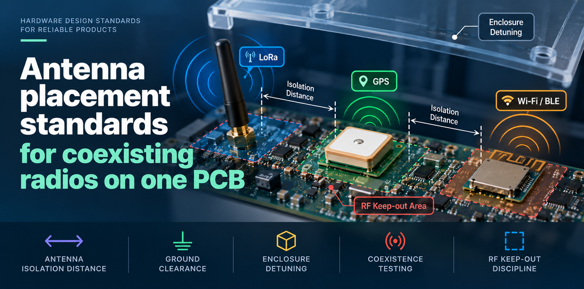
Antenna placement for coexisting radios is set by an isolation budget, not by whatever board edge is left over. On Eversense, our board with LoRa, GPS and a Wi-Fi/BLE combo radio, moving the three antennas to separate edges and restoring each ground clearance raised LoRa-to-GPS isolation from 8 dB to 21 dB against a 16 dB requirement. GPS C/N0 now drops by 1.5 dB during Wi-Fi transmit, down from 9 dB.
This post covers why spacing alone cannot isolate radios on a small board, why our first layout failed, and how to calculate the isolation each radio pair needs. It then covers ground clearance and RF keep-out rules, enclosure detuning, how the mitigation methods compare, and how we test coexistence with an aggressor and victim matrix.
The short version
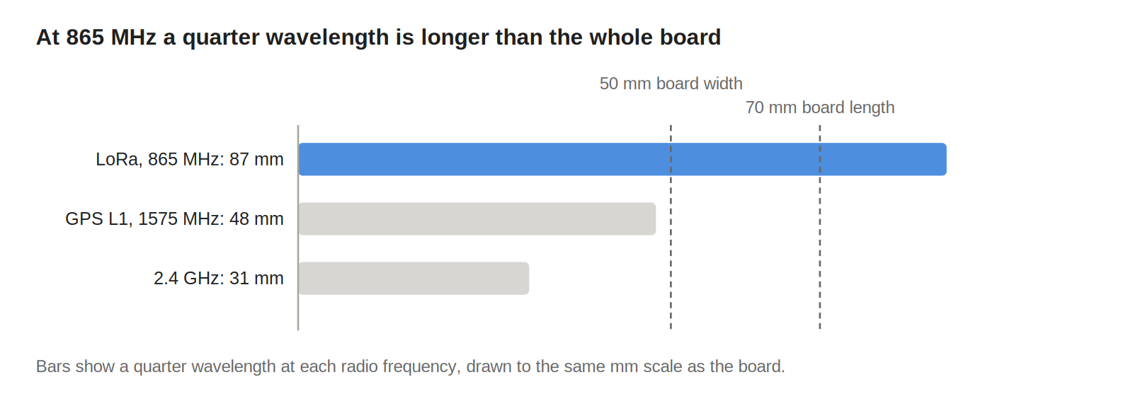
- At 865 MHz a quarter wavelength is about 87 mm, longer than our 70 mm board, so spacing alone cannot deliver LoRa-to-GPS isolation.
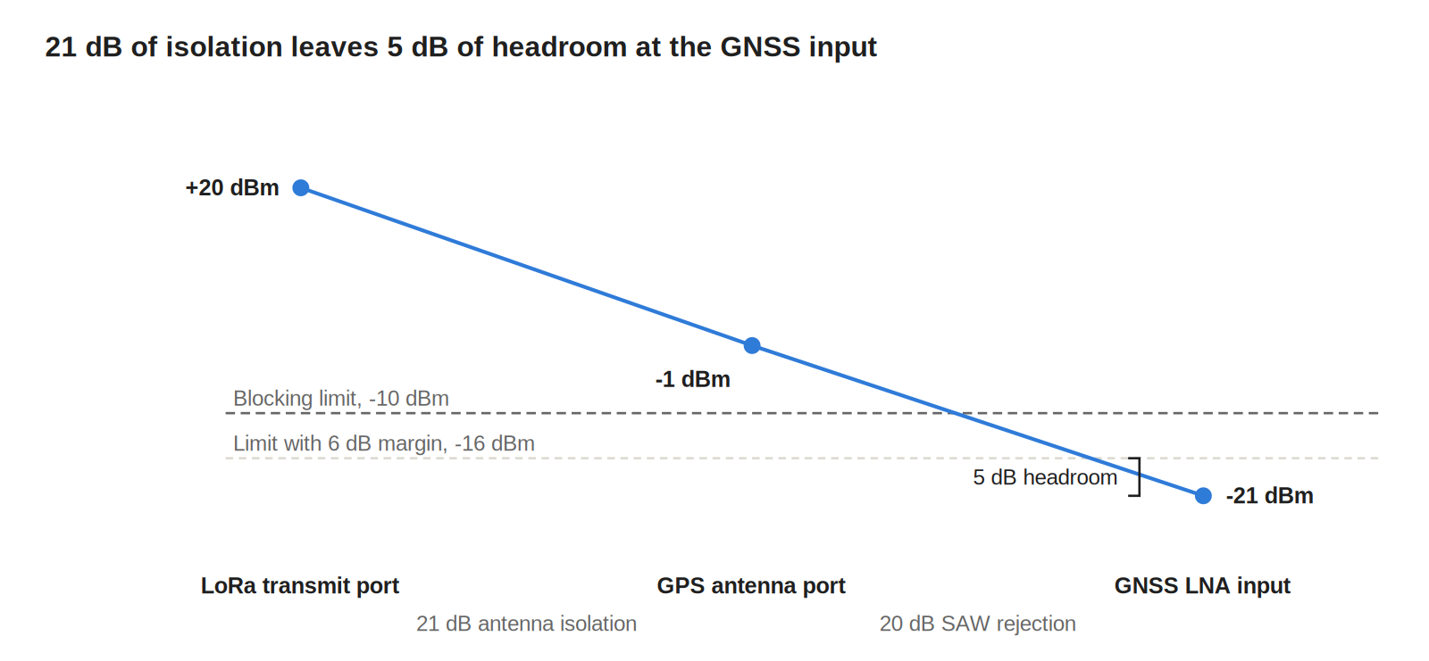
- A +20 dBm LoRa transmitter, a GNSS receiver that tolerates -10 dBm, 20 dB of filter rejection and 6 dB of margin set a 16 dB isolation requirement.
- A 1.5 mm copper encroachment into the 2.4 GHz chip antenna's clearance cut its radiated efficiency from 61% to 38%.
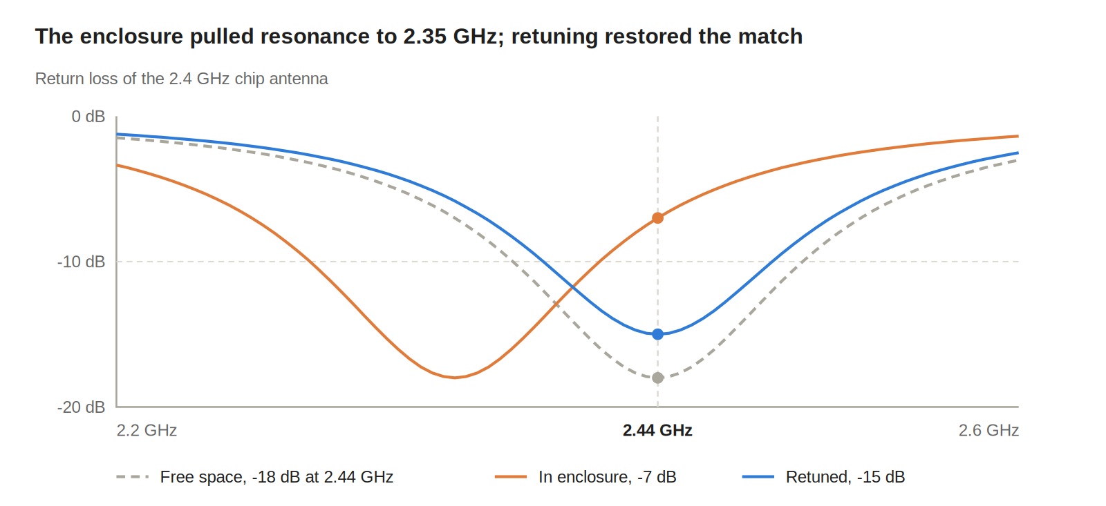
- The 2.5 mm PC/ABS housing pulled the 2.4 GHz resonance from 2.44 GHz down to 2.35 GHz; retuning the match in the enclosure took return loss at 2.44 GHz from -7 dB to -15 dB.
Why spacing alone cannot isolate radios on a small board
Isolation between two antennas grows with distance, but on a small board every antenna uses the same ground plane as part of its radiating structure. Currents from one antenna flow across the copper under the others, so the antennas couple through the ground as well as through the air.
The quarter wavelength shows the scale problem. At 865 MHz it is about 87 mm, at the 1575.42 MHz GPS L1 frequency about 48 mm and at 2.44 GHz about 31 mm. Our board is 50 mm by 70 mm, so the LoRa antenna's ground currents reach every corner.
That leaves four levers, and the standard uses all of them: placement and edge choice, polarization, filtering and transmit timing. Radios are not the only aggressors either. Clock harmonics from fast digital links, like the CSI-2 interface in our dual-camera design on a single CSI-2 port, can land in the GPS band and need the same keep-out discipline.
Why our first antenna layout failed
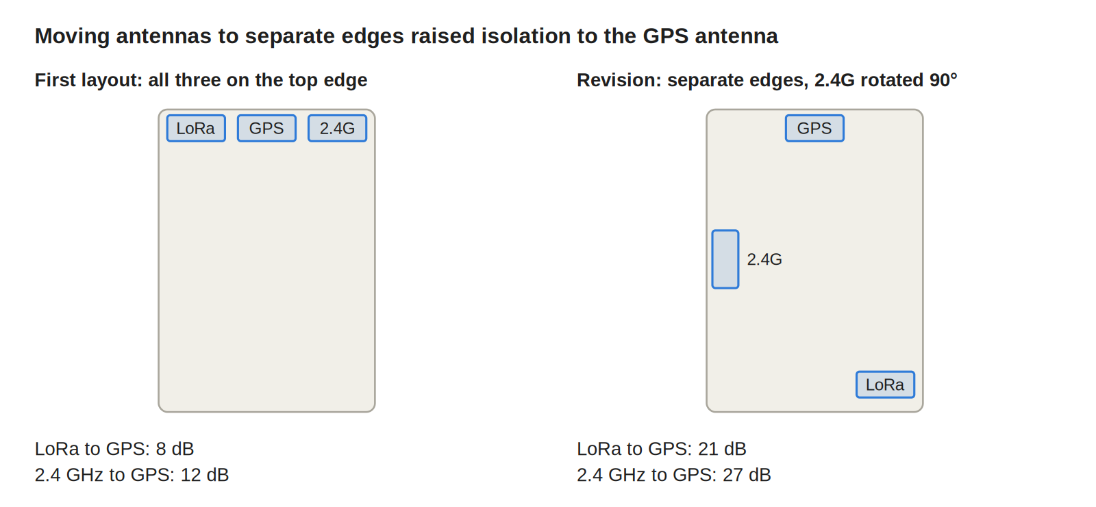
The first Eversense layout put all three antennas along the 50 mm top edge, with the GPS chip antenna between the LoRa and 2.4 GHz antennas. It kept the RF section compact and the feed lines short.
Measured S21 was 8 dB between LoRa and GPS and 12 dB between the 2.4 GHz antenna and GPS. GPS lost lock whenever LoRa transmitted, and C/N0 dropped by 9 dB during Wi-Fi transmit. All three antennas drove currents along the same edge, and the GPS antenna sat where the LoRa ground current was strongest.
The revision placed GPS on the top edge, LoRa at the far end of the bottom edge and the 2.4 GHz chip antenna on a side edge, rotated 90 degrees to the GPS antenna. Isolation rose to 21 dB for LoRa to GPS and 27 dB for 2.4 GHz to GPS.
How to calculate the isolation each radio pair needs
Start from the victim, not the antenna. The isolation required between an aggressor and a victim is:
I_{req} = P_{TX} - P_{block} - R_{filter} + M
P_TX is the aggressor's power at its antenna port, P_block the highest out-of-band power the victim tolerates at its input, R_filter the victim's front-end filter rejection at the aggressor frequency and M the margin, all in dB or dBm.
Step 1: take the aggressor's transmit power
Our LoRa radio transmits at +20 dBm in the 865 MHz band.
Step 2: read the victim's blocking limit
Our GNSS receiver tolerates -10 dBm at 865 MHz before C/N0 degrades. Use the datasheet's blocking figure at the aggressor frequency, not the in-band sensitivity.
Step 3: subtract filter rejection and add margin
The SAW filter ahead of the GNSS LNA rejects 20 dB at 865 MHz. A 6 dB margin covers enclosure, hand and unit variation, giving 20 + 10 - 20 + 6 = 16 dB. The revised layout's 21 dB leaves 5 dB of headroom; the first layout's 8 dB failed by 8 dB.
Step 4: check mixing products, not only pairs
Two transmitters can create a product that lands on a third radio. Wi-Fi channel 7 at 2442 MHz minus LoRa at 866.58 MHz is 1575.42 MHz, exactly GPS L1. Any nonlinear part both signals reach can generate it, including an ESD diode on an antenna port; our post on ESD protection architecture for user-facing ports covers clamp selection. A filter at the GPS input cannot remove an in-band product, so on Eversense LoRa and Wi-Fi never transmit at the same time.
Ground clearance and RF keep-out rules
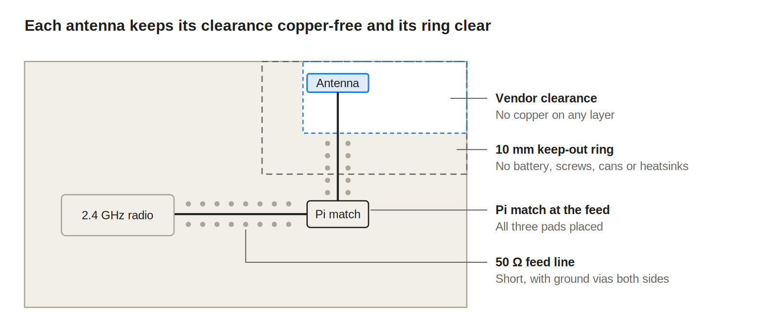
A chip antenna's ground clearance is part of the antenna. The vendor tunes it on a reference board with a defined copper-free area, and copper inside that area shifts its resonance and cuts its efficiency.
On the first layout, a ground pour stitched to a via fence crept 1.5 mm into the 2.4 GHz antenna's clearance. Radiated efficiency fell from 61% to 38%, and no matching change recovered it. Restoring the clearance did. Our keep-out standard for every antenna is:
- No copper on any layer inside the vendor clearance, including inner planes.
- No components, test points or traces inside the clearance.
- Batteries, screws, shield cans and heatsinks at least 10 mm from the clearance edge.
- A 50 Ω feed line, as short as practical, with ground vias along both sides.
- A pi matching network at the antenna feed, with all three pads placed even when only a 0 Ω link is fitted.
Feed-line width comes from the same controlled-impedance tables described in our PCB stack-up standards for controlled impedance. Metal parts that can shift during assembly, like clips and fasteners, get fixed positions in the drawing, the same way as in our heatsink and thermal interface mounting standards.
Enclosure detuning and retuning the match
Plastic near an antenna raises the effective permittivity around it, which lowers its resonant frequency. The closer and thicker the wall, the larger the shift.
In free space, the 2.4 GHz chip antenna showed -18 dB return loss at 2.44 GHz. Inside the 2.5 mm PC/ABS housing, with the wall 1 mm from the antenna, resonance moved to 2.35 GHz and return loss at 2.44 GHz fell to -7 dB. Retuning the pi network in the closed enclosure brought it back to -15 dB.
The GPS antenna needs the same check because its bandwidth is narrow, and a small shift can move L1 off its response. Our rules:
- Tune every antenna inside the final enclosure, with the battery fitted and the lid closed.
- Tune on the product's real mounting surface when that surface is conductive or dense.
- Record matching values per enclosure revision, and retune when wall thickness or material changes.
Coexistence mitigation methods compared
Each method addresses a different coupling path, and none covers all of them.
| Method | What it fixes | Cost | Limit |
|---|---|---|---|
| Edge separation | Coupling through shared edge currents | Layout area | Limited by board size at sub-GHz |
| Orthogonal polarization | Direct coupling between linear antennas | Little, if space allows | Enclosure reflections reduce the gain |
| Restored ground clearance | Lost efficiency and detuning | Board area | Competes with component placement |
| SAW filter at the victim | Out-of-band blocking | BOM cost and insertion loss | No effect on in-band products |
| Filter at the aggressor | Harmonics and spurs in the victim band | BOM cost and transmit loss | Lowers radiated power |
| Transmit time division | Overlapping transmissions and mixing products | Firmware scheduling and latency | Cannot pause GPS reception |
On Eversense, placement and polarization carried LoRa-to-GPS isolation past its 16 dB requirement, and time division handles the Wi-Fi and LoRa mixing product that no amount of isolation removes.
Coexistence testing with an aggressor and victim matrix
Isolation measured with a VNA predicts coexistence; it does not prove it. The proof is each receiver's performance while each transmitter, and each pair of transmitters, is active in the assembled product.
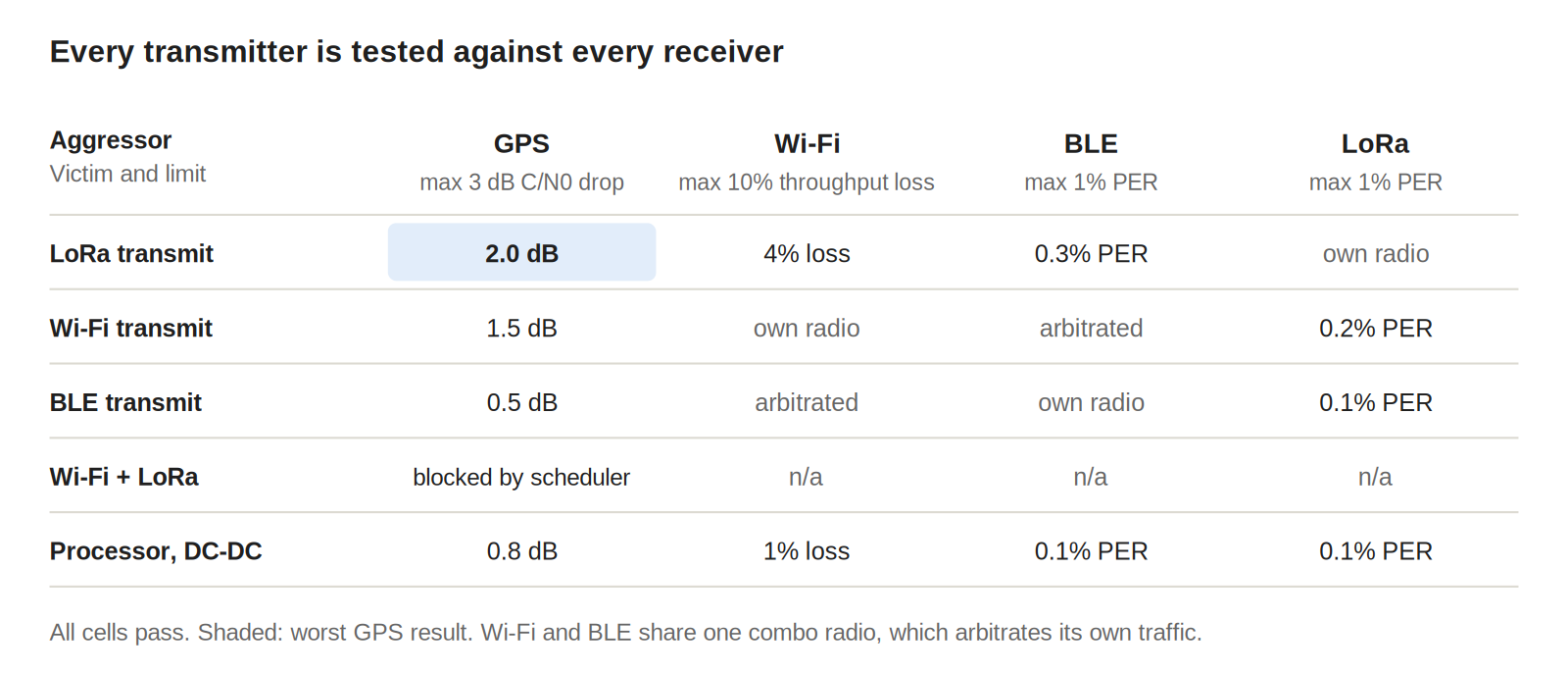
We build a matrix with every transmitter as an aggressor row and every receiver as a victim column, plus rows for the processor, DC-DC converters and other digital sources. Each cell records one metric against a pass limit set before testing:
- GPS: C/N0 drop of 3 dB or less, with a GNSS simulator held at -130 dBm.
- Wi-Fi: throughput loss of 10% or less.
- BLE and LoRa: packet error rate of 1% or less.
Tests run in a shielded enclosure with the unit closed and on battery, so cables do not add coupling paths. On the revised board, the worst GPS cell was a 2 dB C/N0 drop during LoRa transmit. Combined rows, like Wi-Fi channel 7 with LoRa at 866.58 MHz, stay in the matrix to confirm the scheduler never lets them overlap.
What this means for EverBowl
EverBowl™ learns a dog's eating and drinking patterns, and its wireless link is what carries that record off the bowl. The same placement standard applies to its 2.4 GHz antenna: a fixed ground clearance, a match tuned inside the final housing and a coexistence matrix before release, so the link keeps its margin and the record has fewer gaps.
The honest limit: board-level isolation recovers margin on the board, not in the home, so a weak router or a bowl placed beside a metal appliance still limits the link. EverBowl does not diagnose; the value is the record.
Conclusion
Start antenna placement with an isolation budget for every aggressor and victim pair, including mixing products, before any antenna lands on the board. Put antennas on separate edges with orthogonal orientation, protect each vendor clearance as part of the antenna, and tune every match inside the final enclosure. Then prove the result with an aggressor and victim matrix against limits set before testing. More notes like this are in our hardware engineering category.
FAQs
How far apart should antennas be on a PCB?
There is no single distance, because isolation depends on frequency, ground currents and orientation as much as spacing. A useful reference is a quarter wavelength at the lowest frequency, but on small boards that is often longer than the board, so placement on separate edges, polarization and filtering have to supply the rest.
How much isolation do two antennas need?
Calculate it from the aggressor's transmit power, the victim's blocking limit, the victim's filter rejection and a margin. In our example, that came to 16 dB between a +20 dBm LoRa transmitter and a GNSS receiver.
What is antenna ground clearance?
It is the copper-free area the antenna vendor specifies around a chip antenna, on every layer. The vendor tunes the antenna with that clearance in place, so copper inside it shifts resonance and lowers efficiency.
Why does an enclosure detune an antenna?
Plastic has a higher permittivity than air, so a nearby wall lowers the antenna's resonant frequency. The fix is to tune the matching network with the antenna inside the closed, final enclosure.
How do you test radio coexistence?
Measure each receiver's performance while each transmitter, and each combination of transmitters, is active in the assembled product. Record a metric per cell, such as GPS C/N0 drop or packet error rate, against limits set before the test.
References
- u-blox, GNSS antennas: RF design considerations for u-blox GNSS receivers (UBX-15030289), application note.
- Texas Instruments, AN058 Antenna Selection Guide (SWRA161), application note.
- Texas Instruments, DN035 Antenna Selection Quick Guide (SWRA351), design note.
- u-blox, SARA-R5 positioning implementation, cellular and GNSS RF coexistence (UBX-20012413), application note.