Power architecture for modular add-on boards with unknown loads
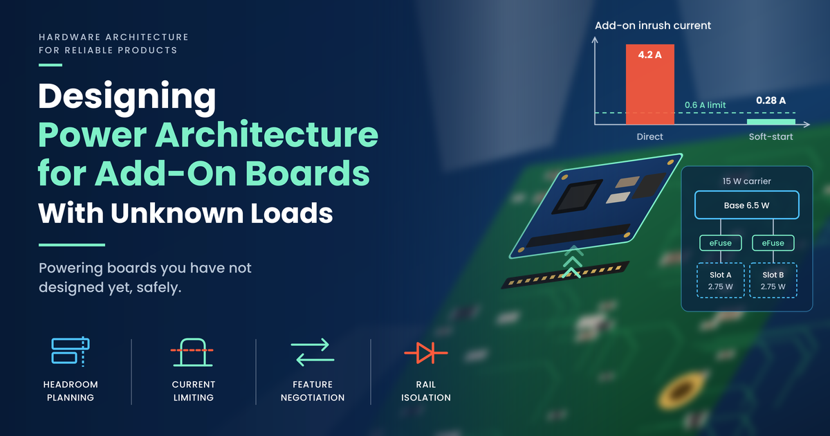
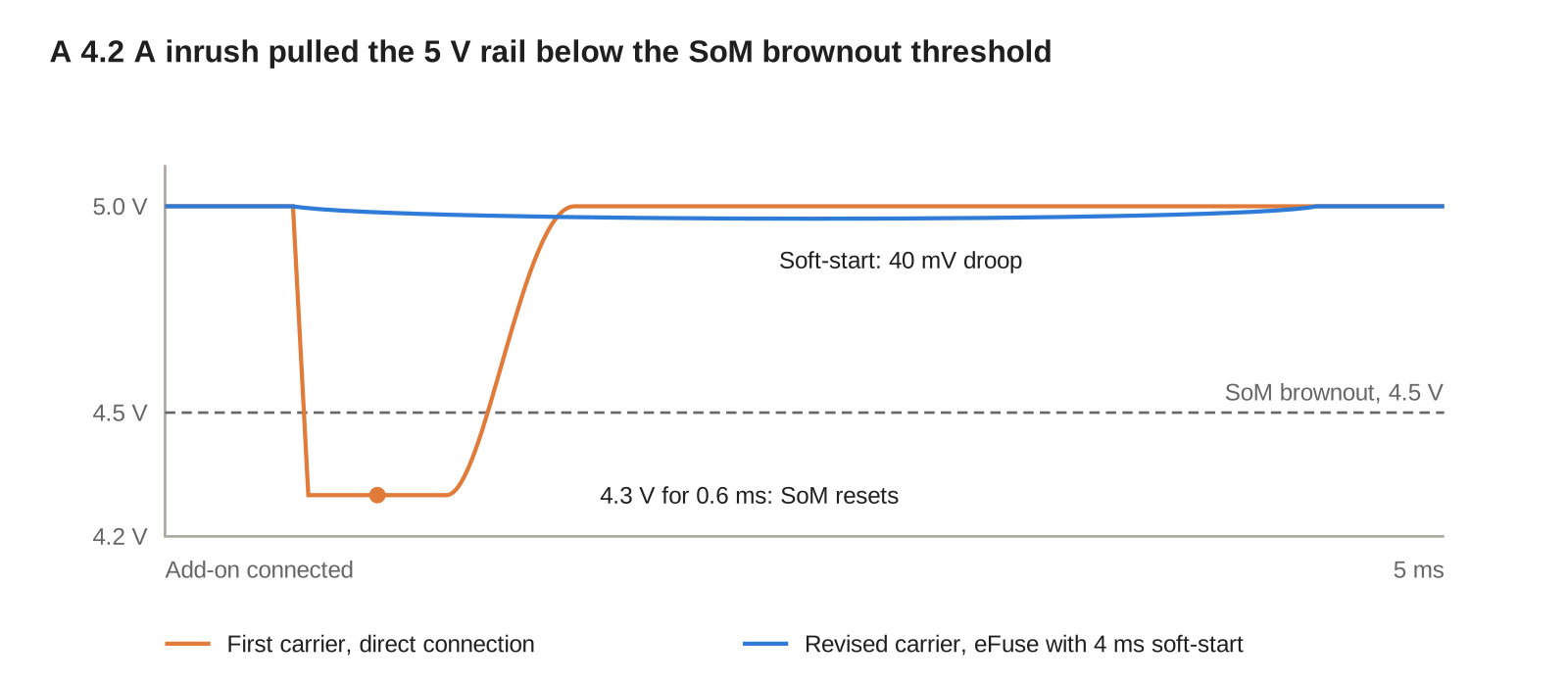
A carrier board that accepts add-on boards it has never seen needs a power budget per slot, a current limit per slot and a negotiation step before any main rail turns on. On our AM62A7 carrier, a per-slot eFuse with a 4 ms soft-start cut add-on inrush from 4.2 A to 0.28 A, and the 5 V rail now droops by 40 mV at power-up instead of collapsing to 4.3 V and resetting the SoM. Each add-on now declares its load from an ID EEPROM before the carrier grants power.
This post covers why an unknown load breaks a fixed power budget, what failed on our first carrier, and how to plan expansion headroom per slot. It then covers per-slot current limiting, feature negotiation, rail isolation against back-feed, how the protection options compare, and how we test tolerance to loads we cannot predict.
The short version
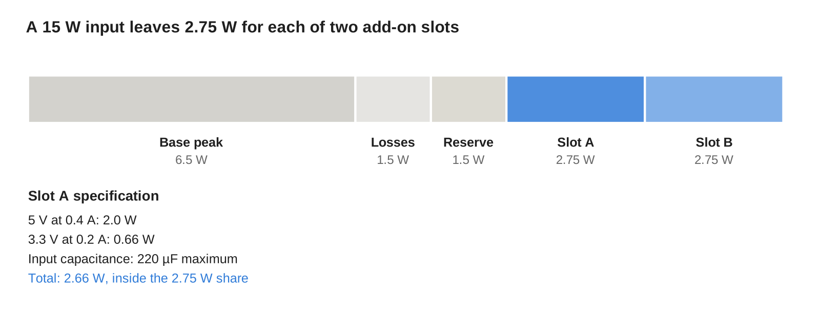
- A 15 W input, less a 6.5 W base peak, 1.5 W of conversion loss and a 1.5 W reserve, leaves 5.5 W, or 2.75 W per slot across two slots.
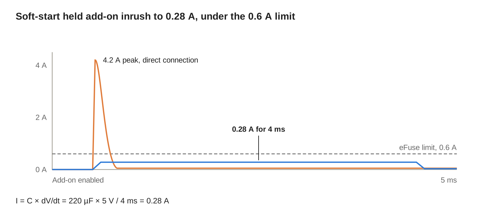
- A 220 µF add-on input capacitor charged through a 4 ms soft-start draws 0.28 A, against a 4.2 A peak when connected straight to the 5 V rail.
- An unpowered add-on back-fed our 3.3 V rail to 1.9 V through its I2C pull-ups until we added reverse-current blocking and powered-off-tolerant buffers.
- An add-on with no readable ID gets a minimal profile of 3.3 V at 100 mA and no 5 V.
Why an unknown load breaks a fixed power budget
A fixed power budget assumes every load is known at design time. Add-on boards break that assumption, because they are often designed later, by another team, for a feature the carrier was never sized around.
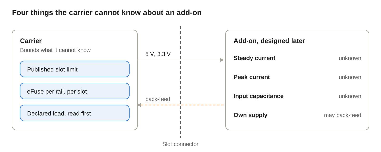
Three properties of an add-on are unknown when the carrier is designed: its steady current, its peak current and its input capacitance. A fourth is easy to miss: the add-on may carry its own supply, such as a battery or a USB port, and drive current back into the carrier.
The carrier cannot know these values, so it has to bound them. Each slot gets a published limit, hardware that enforces it, and a way for the add-on to declare its needs before power is applied. How we rank loads when the total budget runs short is covered in our post on hardware priority rules when power budget is limited.
What failed on our first carrier
The first carrier routed its 5 V and 3.3 V rails straight to the add-on connector, with one 1.5 A polyfuse shared by both slots. It worked with the first add-on, a small sensor board.
The radar add-on broke it. Its 220 µF input capacitor drew a 4.2 A inrush peak, the 5 V rail dipped to 4.3 V for 0.6 ms, and the SoM's 4.5 V brownout detector reset the system. The polyfuse was too slow to react to the inrush and, being shared, a shorted add-on during bring-up took the whole carrier down with it.
The third failure was quieter. With the carrier off and a bench-powered add-on attached, the add-on's I2C pull-ups back-fed the carrier's 3.3 V rail to 1.9 V, enough to half-power the SoM's I/O ring.
How to plan expansion-board headroom
The power left for add-ons is what remains after the carrier's own worst case, divided across the slots:
P_{slot} = \frac{P_{in} - P_{base} - P_{loss} - P_{reserve}}{N}Step 1: measure the base peak, not the average
Our carrier's input is 5 V at 3 A, or 15 W. Its base peak, with Wi-Fi transmitting and the NPU running inference at once, is 6.5 W. The average is far lower, but the add-on budget has to hold at the peak.
Step 2: add conversion losses at that peak
The regulators feeding the base and slot rails lose 1.5 W at full load. Measure this at the peak load point, because converter efficiency changes with load.
Step 3: hold a reserve
We reserve 10 percent of the input, 1.5 W, for component drift, a weaker adapter and future firmware load. Our post on voltage margining for long-term component aging explains why that drift is real.
Step 4: divide and publish the slot limit
That leaves 5.5 W, or 2.75 W per slot across two slots. We publish it as a slot specification: 5 V at 0.4 A, 3.3 V at 0.2 A and no more than 220 µF of input capacitance, which totals 2.66 W and stays inside the slot's share.
Current limiting per slot
Every rail on every slot now has its own limiter: an eFuse set to 0.6 A on the 5 V rail and a current-limited load switch at 0.3 A on the 3.3 V rail. A fault on one slot trips that slot only.
The eFuse's soft-start sets the inrush. The capacitor charges at the slew rate the eFuse enforces, so the current is:
I_{inrush} = C \frac{dV}{dt}With 220 µF ramped to 5 V over 4 ms, the inrush is 0.28 A, well under the 0.6 A limit. The 5 V rail at the SoM now droops by 40 mV at power-up.
We use latch-off rather than auto-retry. An auto-retry eFuse keeps pulsing current into a short, heating the add-on on every cycle. Our firmware reads the fault flag, logs it, waits 1 s and retries once; a second fault keeps the slot off until the add-on is removed. Each eFuse also reports its current through an IMON pin that firmware samples at 1 kHz. When a slot fault coincides with other faults, the order of response follows our priority encoding for simultaneous fault conditions.
Feature negotiation before power-up
Current limits protect the carrier, but they cannot tell an add-on that draws too much from one that is broken. Negotiation lets each add-on state its needs first, so the carrier only grants power it can supply.
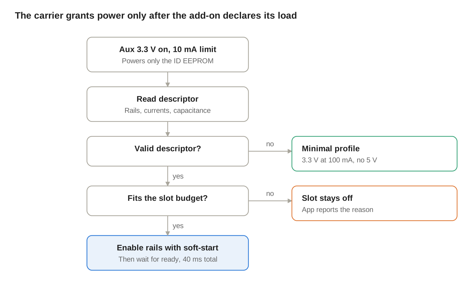
Each slot has an always-on 3.3 V auxiliary pin, limited to 10 mA, that powers only the add-on's ID EEPROM. The carrier reads a descriptor from it before any main rail turns on:
/* Add-on descriptor, read from the slot ID EEPROM */
struct addon_desc {
    uint16_t magic;          /* format marker */
    uint8_t  version;        /* descriptor format version */
    uint8_t  board_type;     /* radar, speaker, sensor, ... */
    uint16_t i5v_cont_ma;    /* declared 5 V continuous */
    uint16_t i5v_peak_ma;    /* declared 5 V peak, 10 ms */
    uint16_t i3v3_cont_ma;   /* declared 3.3 V continuous */
    uint16_t cin_uf;         /* total input capacitance */
    uint8_t  own_supply;     /* 1 if it can back-feed */
    uint8_t  crc8;
};
The carrier checks the declared load against the slot limit and the budget left after the other slot, enables the rails with soft-start, then waits for the add-on's ready signal. The full sequence takes 40 ms. A descriptor that asks for more than the slot allows leaves the slot off, and the app reports why.
Unknown-load tolerance comes from the fallback. An add-on with a blank, unreadable or corrupt descriptor gets a minimal profile of 3.3 V at 100 mA and no 5 V, enough for a simple sensor and too little to hurt the carrier. Changing slot power while the system runs follows our rules for preventing unsafe reconfiguration while subsystems are active.
Rail isolation between carrier and add-ons
Back-feed happens when an add-on, or anything attached to it, drives current into the carrier while the carrier is off. Pull-ups tied to the add-on's own rail and add-ons with their own battery are the usual sources.
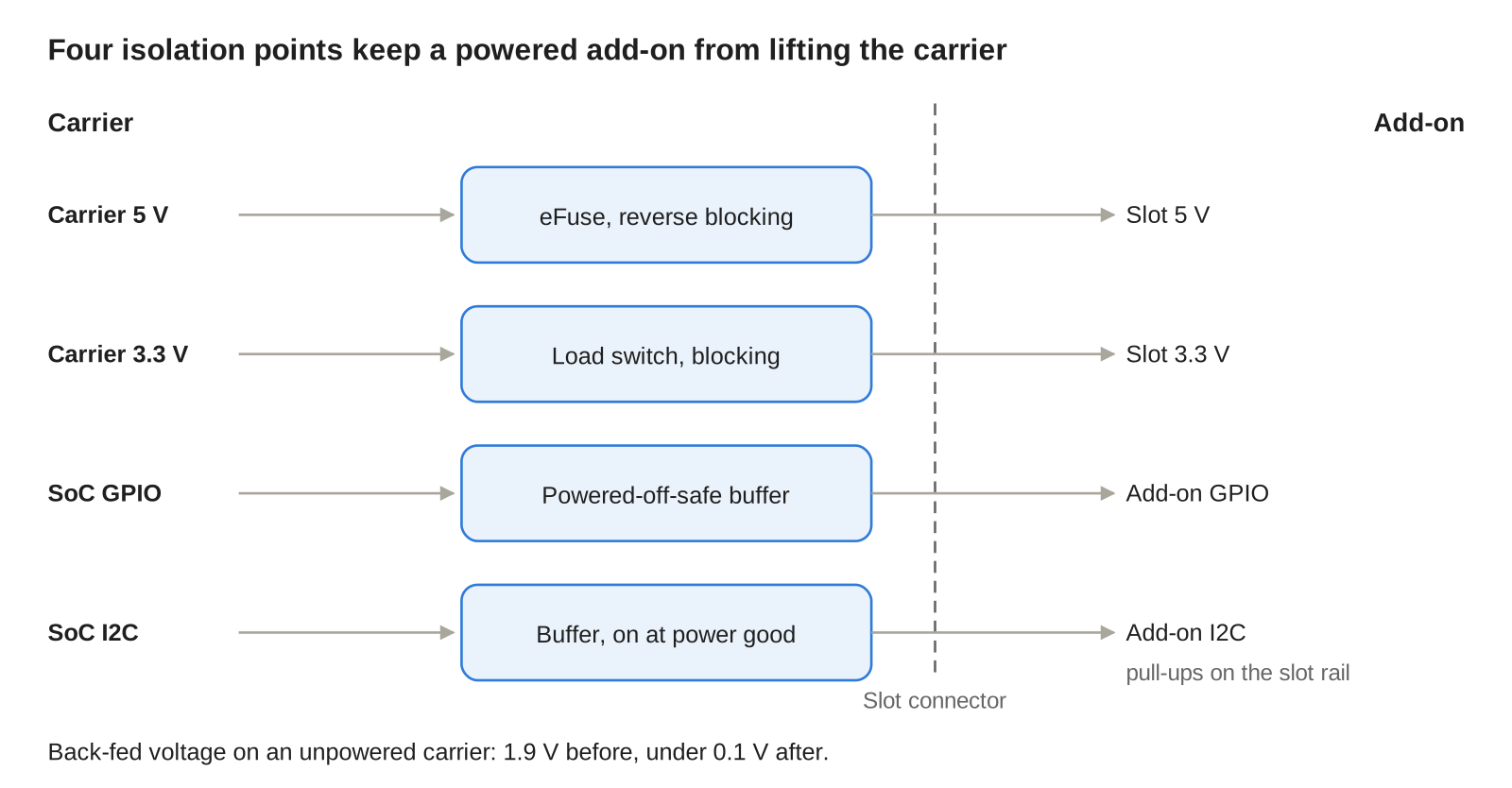
We now isolate every slot in four ways:
- Each slot eFuse blocks reverse current, so a powered add-on cannot lift a carrier rail.
- Signals cross the connector through buffers with powered-off protection, rated to hold their inputs at high impedance with no supply.
- Add-on pull-ups tie to the slot rail, never to a carrier rail.
- The I2C path to the add-on passes through a buffer that is enabled only after the slot reports power good.
With these changes, the back-fed voltage on an unpowered carrier fell from 1.9 V to under 0.1 V. Slot enables share the same discipline as our kill switch for several modules on a pin-starved carrier: every enable defaults to off when its driver is unpowered.
Add-on power protection options compared
Each option adds protection the one above it lacks. The table compares how each handles the three failures our first carrier hit.
Option | Inrush control | Fault isolation | Back-feed blocking | Cost |
|---|---|---|---|---|
Direct connection | None | None | None | Lowest |
Shared polyfuse | None | Slow and shared | None | Low |
Load switch per slot | Fixed slew rate | Limited, per slot | Only on some parts | Low |
eFuse per slot | Programmable soft-start | Fast, per slot | With reverse blocking | Moderate |
eFuse per slot plus negotiation | Set per declared load | Fast, and checked before power-up | Yes | Moderate, plus an EEPROM per add-on |
On our carrier, the last row costs one eFuse, one load switch and one buffer per slot, plus an EEPROM on each add-on. It is the only row that handles a load the carrier has never seen.
Testing unknown-load tolerance
You cannot test against add-ons that do not exist yet, so we test against a dummy add-on that can behave like any of them. It combines a programmable electronic load, a switchable capacitor bank and a bench supply for back-feed tests.
The test sweeps five conditions on each slot:
- Steady load from zero to 120 percent of the slot limit.
- Load steps from 10 percent to 100 percent in 10 µs.
- Input capacitance up to 470 µF, more than twice the published limit.
- A dead short on each rail.
- An unpowered carrier with a powered add-on attached.
Pass criteria are set before testing: base rails stay within 3 percent, the SoM never resets, a faulted slot trips without disturbing the other slot, and back-fed voltage stays under 0.1 V. The revised carrier passed 500 plug cycles across all conditions with zero SoM resets.
What this means for EverBowl
EverBowl™ learns a dog's eating and drinking patterns, and add-on boards let it gain new abilities, such as a speaker so owners can talk to their dog, without a new carrier. Because each add-on declares its load and every slot is limited and isolated, a new module cannot reset the bowl or interrupt the record it is building.
The honest limit: negotiation trusts the descriptor, so an add-on that understates its load will still be cut off by its current limit mid-use, which protects the carrier but stops that feature. EverBowl does not diagnose; the value is the record.
Conclusion
Start with a per-slot budget taken from the carrier's peak load, conversion losses and a reserve, and publish it as a slot specification. Enforce it with an eFuse per rail per slot, set soft-start from the largest capacitance you allow, and block reverse current at every slot. Then make each add-on declare its load before power-up, and give anything unidentified a minimal profile. More notes like this are in our hardware engineering category.
FAQs
How much power should I reserve for expansion boards?
Subtract the carrier's peak load, conversion losses and a reserve from the input power, then divide by the number of slots. In our example, a 15 W input left 2.75 W per slot across two slots.
How do you limit inrush current from an add-on board?
Use an eFuse or load switch with a controlled soft-start. The inrush current equals the input capacitance times the voltage slew rate, so a 220 µF load ramped to 5 V over 4 ms draws about 0.28 A.
Should an eFuse use latch-off or auto-retry?
Latch-off is usually safer for add-on slots, because auto-retry keeps pulsing current into a short. Firmware can still retry once after a delay and keep the slot off if the fault returns.
What is back-feeding and how do you prevent it?
Back-feeding is current flowing from an add-on into an unpowered carrier, often through pull-ups or I/O pins. Reverse-current blocking on each slot rail, powered-off-tolerant buffers and pull-ups tied to the slot rail prevent it.
How can a carrier support add-ons that do not exist yet?
Give every add-on an ID EEPROM with a load descriptor that the carrier reads on a low-power auxiliary rail before enabling main power. Anything without a valid descriptor gets a minimal, safe power profile.
References
- Texas Instruments, Basics of eFuses (SLVA862), application note.
- Texas Instruments, Basics of Power Switches: eFuses (SLVA927), application note.
- Texas Instruments, Reducing Power Loss and Overheating During Faults with eFuses (SLVAED9), application note.
- Bill Schweber, Get Comfortable with eFuses: They Have Many Useful Features, DigiKey.