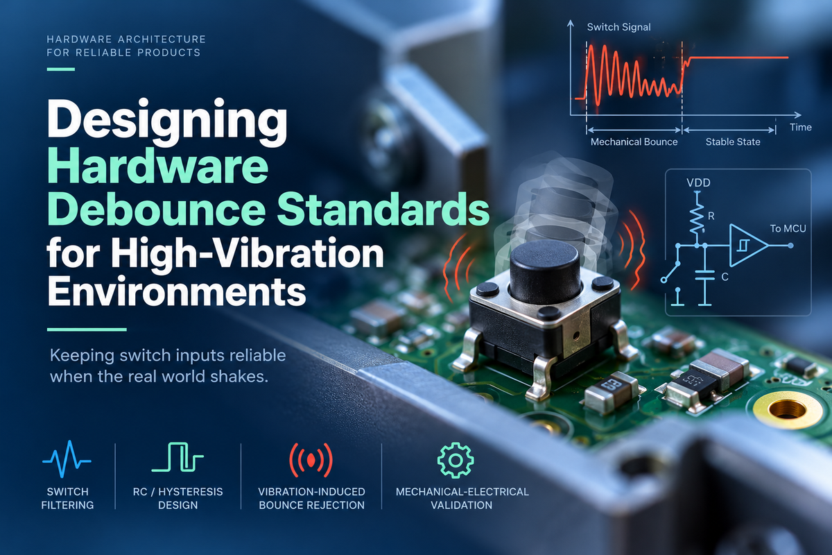
Hardware debounce circuit design for high-vibration environments
A hardware debounce circuit for a high-vibration environment needs a measured time window for both edges, not just a capacitor across the switch. In our reference input, a 100 kΩ pull-up and a 100 nF capacitor feeding a Schmitt-trigger input delay the release by 11.1 ms, and a 10 kΩ series resistor sets the press delay to about 1.3 ms. Under 2 hours per axis of 10 to 500 Hz random vibration at 1.0 g RMS, that circuit reduced false activations from 37 to 0.
This post covers how vibration-induced switching differs from contact bounce, why a bounce-sized RC filter failed on our first build, and how to calculate press and release delays at tolerance limits. It then covers where hysteresis fits, how the common debounce approaches compare, and how to qualify a switch as one mechanical and electrical system.
The short version
- A 100 kΩ pull-up with a 100 nF capacitor has a 10 ms time constant, but it filters only the release edge; without a series resistor the press edge passes in microseconds.
- Adding a 10 kΩ series resistor between the switch and the capacitor sets the press delay to about 1.3 ms and leaves a 0.3 V low level on a 3.3 V rail.
- Resistor and capacitor tolerance alone move the 11.1 ms release delay between 9.9 ms and 12.3 ms, so the operating window must hold at both limits.
- Our acceptance criterion was zero false activations and zero missed presses over 2 hours per axis of the 10 to 500 Hz, 1.0 g RMS profile on 5 assembled units.
Contact bounce and vibration-induced switching are different problems
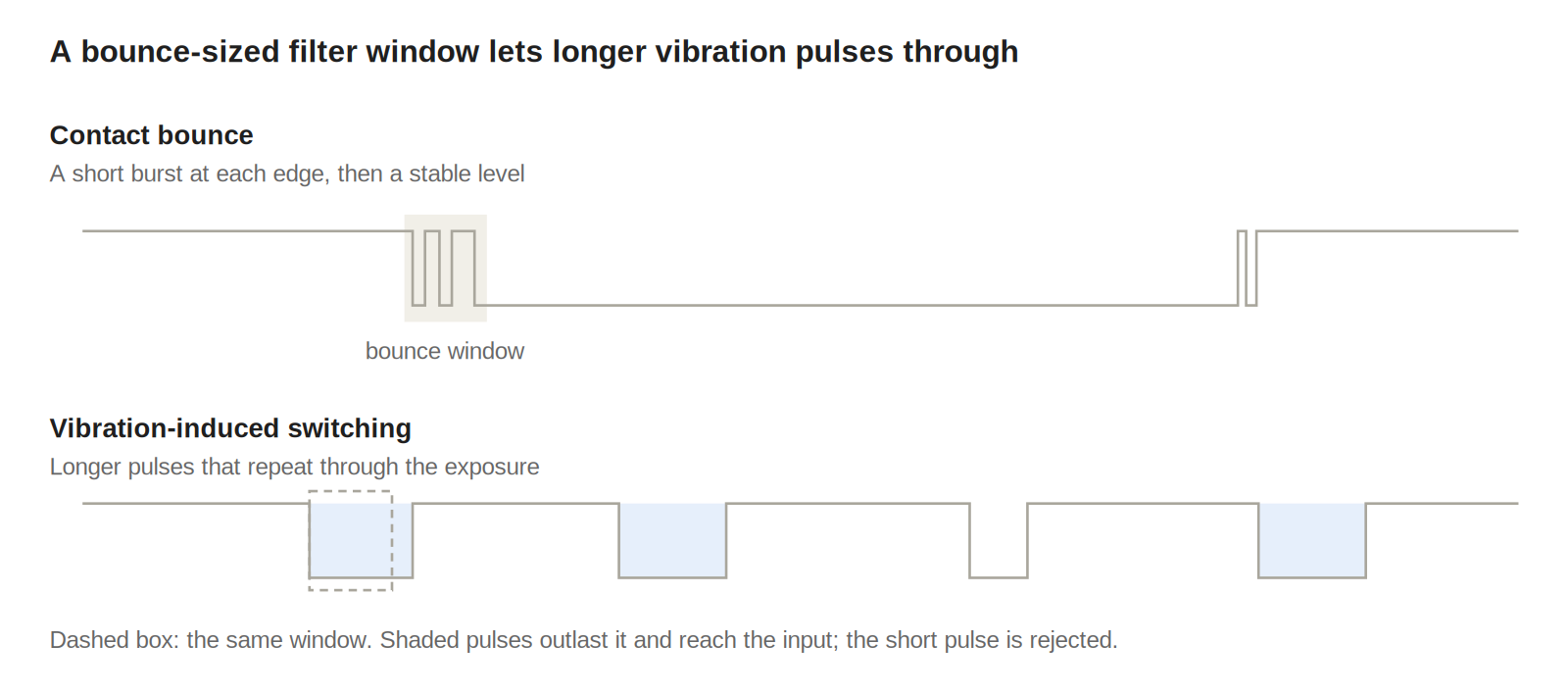
Contact bounce happens when contacts make or break. The transitions sit in a short interval around the switching event, under 1 ms on the tactile switch we use.
Vibration-induced switching has a different cause. Mechanical movement disturbs the contact, moves the actuator or changes contact force, so transitions can last longer and repeat for as long as the vibration does.
That difference decides the filter. A filter sized for bounce can still pass a longer vibration pulse, and firmware may then read repeated presses, a release followed by a press, or an unintended long press. Before layout, the input requirement should state five limits:
- The shortest intended press that must be detected.
- The longest unintended pulse that must be rejected.
- The vibration profile and mounting condition.
- The maximum acceptable response delay on each edge.
- The required behavior if the input never settles.
Why our first RC filter failed under vibration
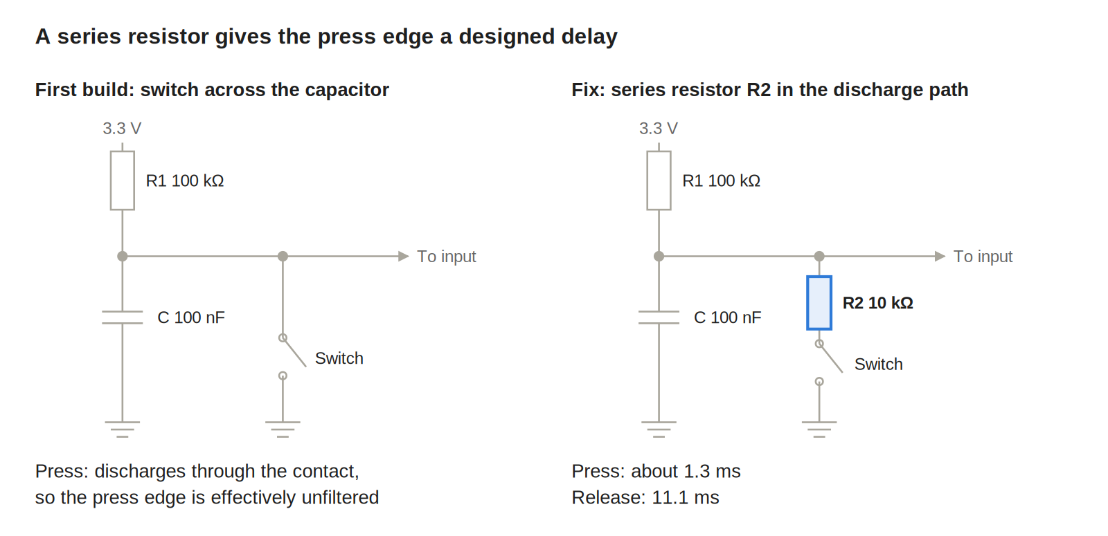
Our first build placed the switch directly across the capacitor, with a 100 kΩ pull-up and 100 nF to ground. On the bench the filtered waveform looked clean and every press registered.
Under the 10 to 500 Hz, 1.0 g RMS profile, we logged 37 false activations across three axes at 2 hours per axis. The cause was the discharge path. When the switch closes, the capacitor discharges through the contact resistance, a fraction of an ohm, so the press edge is effectively unfiltered and every brief vibration-induced closure pulls the input low.
The release edge was filtered by the 10 ms time constant, which is why the circuit looked correct when we scoped releases. The fix adds a resistor in the discharge path so both edges get a designed delay.
How to calculate RC debounce delay for both edges
The time constant τ = R × C is a starting point, not the debounce time. The logic state changes only when the voltage crosses the input threshold, and the two edges usually see different resistances. For any first-order edge, the threshold-crossing time is:
$$t = R C \ln\frac{V_0 - V_\infty}{V_{th} - V_\infty}$$
Here V0 is the starting voltage, V∞ the voltage the node settles to and Vth the input threshold. The example uses a 3.3 V rail, a switch to ground, a 100 kΩ pull-up (R1), a 10 kΩ series resistor (R2) from the switch to the capacitor node, and 100 nF. Thresholds are taken as 0.3 VDD and 0.7 VDD; use the guaranteed values from your input's datasheet.
Step 1: calculate the release delay
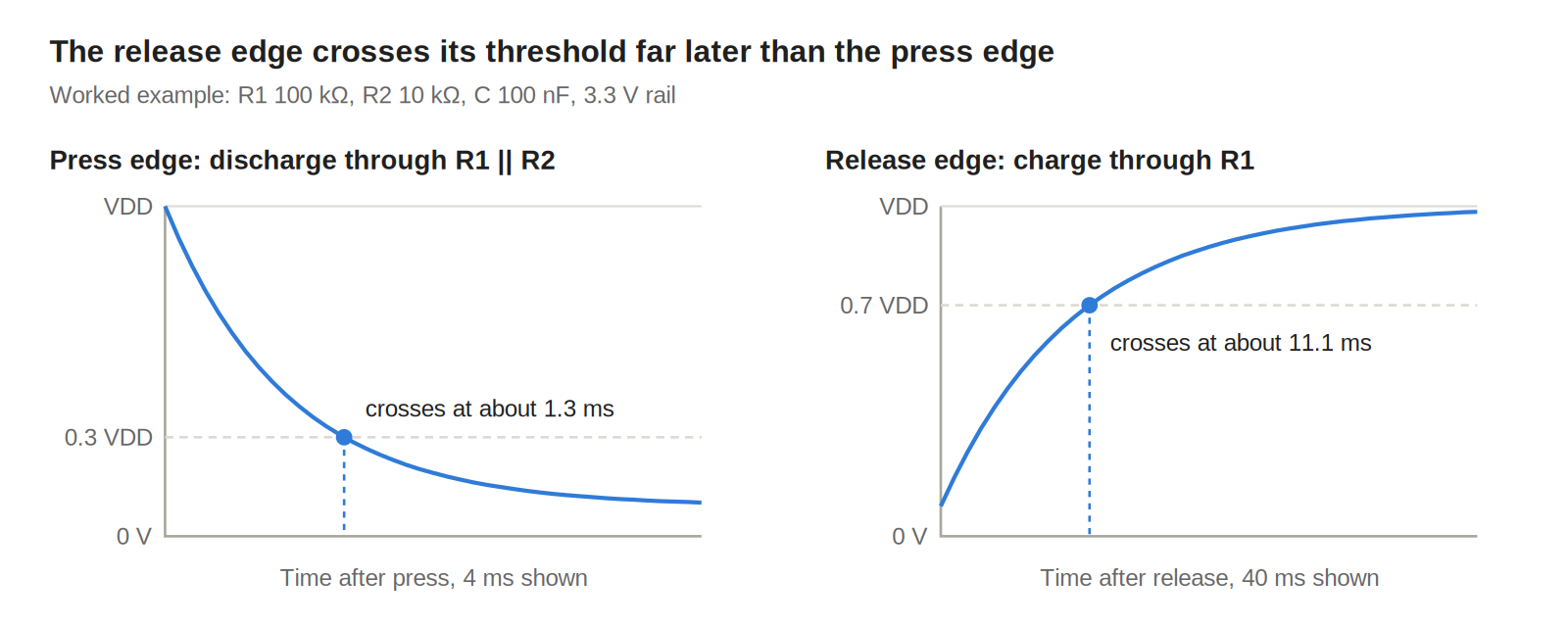
With the switch open, the capacitor charges through R1 from the pressed level toward VDD. Starting at 0.091 VDD and crossing 0.7 VDD with a 10 ms time constant gives a release delay of 11.1 ms.
Step 2: calculate the press delay
With the switch closed, the node discharges through R1 and R2 in parallel, 9.09 kΩ, toward a divider level of 0.30 V. Crossing 0.3 VDD from VDD takes about 1.3 ms. Without R2, the same edge takes microseconds, which is the failure described above.
Step 3: repeat at tolerance limits
With 1 percent resistors and a 10 percent capacitor, the release delay ranges from 9.9 ms to 12.3 ms and the press delay from 1.2 ms to 1.5 ms. X7R capacitance also falls with DC bias and temperature, and input leakage or an enabled internal pull-up shifts both edges. The method we use to budget this kind of drift over a product's life is in our post on voltage margining for long-term component aging.
The asymmetry between edges can be acceptable, but it must be a design choice. The standard records the expected delay for each edge, not a single RC value.
Add hysteresis with a Schmitt-trigger input
An RC filter slows the edge, and a slow edge near the logic threshold can chatter. A Schmitt-trigger input uses separate rising and falling thresholds, so a small disturbance near one threshold does not reverse the output.
The input path we standardize on has five stages, each with one job.
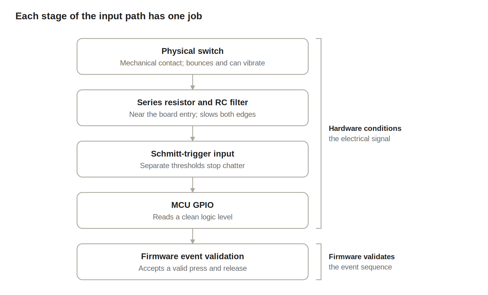
The RC network attenuates short pulses and the hysteresis prevents threshold chatter; one does not replace the other. If the GPIO's hysteresis is not guaranteed over supply and temperature, add an external Schmitt buffer and check its thresholds, output levels, power-up state and propagation delay.
Place the filter close to where the signal enters the board, so a long trace or cable is not picking up interference ahead of it. For a switch on a cable, that entry point usually also carries the ESD clamp. Our post on ESD protection architecture for user-facing ports covers clamp placement, and any series resistance it adds belongs in the delay calculation above.
Hardware vs software debounce: the approaches compared
No single technique rejects every false activation. The table compares what each approach rejects, what it costs in response time and where it stops working.
| Approach | Rejects | Response cost | Limit |
|---|---|---|---|
| RC with switch across the capacitor | Short pulses on release only | Release delay | Press edge is unfiltered; slow edge can chatter |
| RC with series resistor | Short pulses on both edges | Designed delay per edge | Passes a vibration pulse as long as a real press |
| RC plus Schmitt trigger | Short pulses and threshold chatter | Adds buffer propagation delay | Same duration limit as the row above |
| Firmware debounce only | Pulses shorter than the sample window | Sample window plus scan interval | Raw edges still reach interrupts and wake logic |
| RC, Schmitt and firmware sequence check | Isolated pulses without a valid press and release | Time to confirm the sequence | Must not delay safety-critical inputs |
| Mechanical fix to mount or switch | The vibration path itself | None at the input | Needs a board or enclosure change |
When a vibration pulse matches a real press in duration and level, only the last two rows help. That is the point where the mechanical design has to change, not the filter.
Validate the switch as a mechanical and electrical system
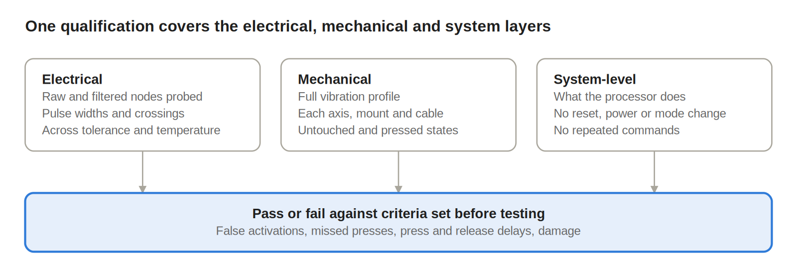
A clean waveform on a stationary bench does not qualify a debounce circuit. The switch, enclosure, fasteners, cable and PCB form one system, and the test has to exercise all of it.
Electrical validation
Probe the raw switch node and the filtered output. Record bounce duration, pulse widths, threshold crossings and the delay from actuation to the recognized event, at tolerance limits and across supply and temperature.
Mechanical validation
Run the assembled product through its vibration profile on each relevant axis, mounting configuration and cable arrangement. Test both untouched and deliberately pressed conditions; a switch that stays quiet but misses a real press during vibration has still failed.
System-level validation
Watch what the processor does with the signal. Confirm that no disturbance triggers a power transition, reset, mode change or repeated command.
For each run, record false activations, missed presses, press and release delays, any change in behavior after exposure and any mechanical damage. Set acceptance criteria before testing; ours is in the short version above. "The switch is vibration resistant" is not a verifiable requirement.
The design review also covers switch retention, PCB support near the footprint, cable strain relief and probe access to the raw and filtered nodes. Switch lots, enclosure tolerance, fastener torque and assembly preload all change mechanical behavior. We control torque and preload the same way as in our heatsink and thermal interface mounting standards, as assembly parameters that belong in the qualification plan.
Define what happens when the input never settles
A damaged switch, contaminated contact, broken cable or sustained load can leave an input stuck asserted or continuously unstable. The architecture has to define the response before it happens.
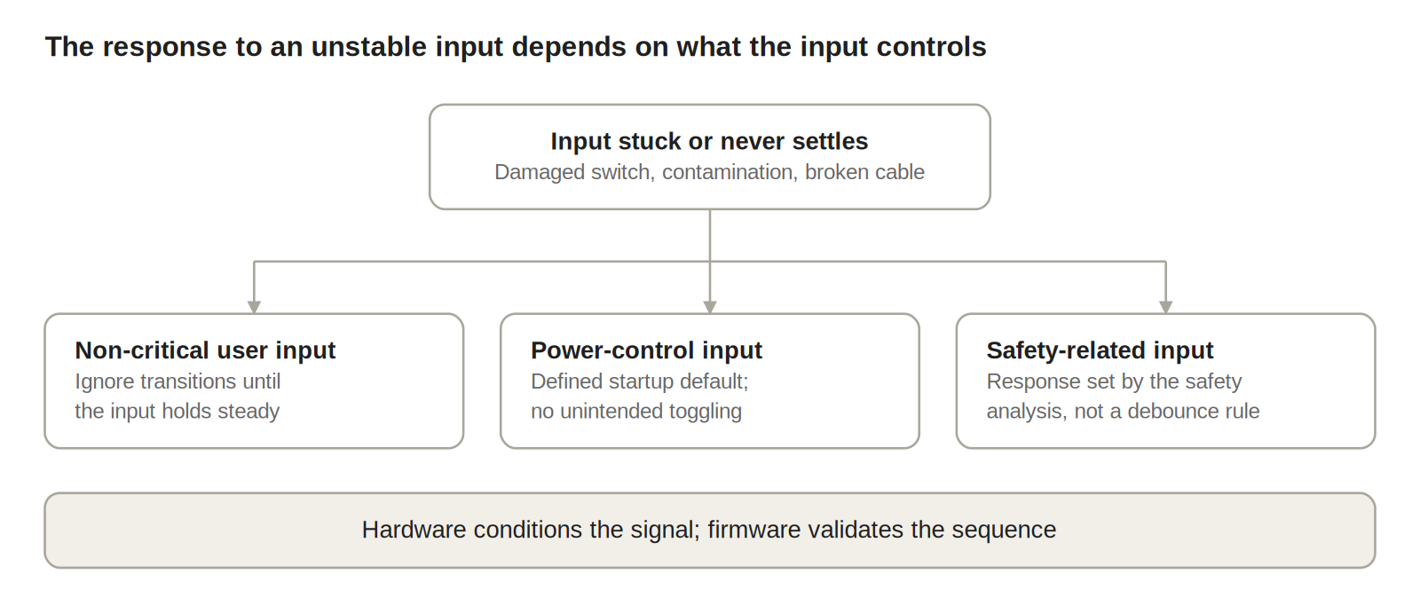
For a non-critical user input, firmware can ignore transitions until the input holds a stable state. For a power-control input, the design needs a defined startup default and protection against unintended toggling; shared power-control lines raise the same question, covered in controlling several modules from a pin-starved carrier. For a safety-related input, the response comes from the safety analysis, not from a generic debounce rule.
Write down the division of work. Hardware conditions the electrical signal; firmware validates the event sequence and applies the product's interaction rules. Neither should assume the other handles every vibration failure.
What this means for EverBowl
EverBowl™ learns a dog's eating and drinking patterns over months, and that record is only as useful as it is continuous. A false press that resets the power button or changes a mode leaves a gap no later data can fill, so every physical input on EverBowl is qualified as a mechanical and electrical system before it ships.
The honest limit: a debounce circuit reduces false inputs, but it cannot fix a switch that moves in its mount, so where testing shows that, the mount changes rather than the filter. EverBowl does not diagnose; the value is the record.
Conclusion
Start each switch input with a written window: the shortest press to detect, the longest pulse to reject and the delay allowed on each edge. Calculate both edges at tolerance limits, add hysteresis where the edge is slow, and validate the assembled product against criteria set before the test. If a vibration pulse still looks like a real press, fix the mount or the switch instead of growing the filter. More design notes like this are in our hardware engineering category.
FAQs
How do you calculate an RC debounce time?
Use the threshold-crossing time, not τ alone: t = RC × ln((V0 − V∞) / (Vth − V∞)). Calculate it separately for the press and release edges, because they usually see different resistances, and repeat it at component tolerance limits.
What is the difference between contact bounce and vibration-induced switching?
Contact bounce is a short burst of transitions when contacts make or break. Vibration-induced switching comes from mechanical movement of the switch or its mount, so it can last longer and repeat throughout the exposure, which a bounce-sized filter may not reject.
Do I need a Schmitt trigger if I already have an RC filter?
Usually, yes. The RC filter slows the edge, and a slow edge near a single threshold can chatter. Hysteresis gives the rising and falling edges separate thresholds, so the output switches once.
Is hardware or software debounce better?
They solve different parts of the problem. Hardware conditions the signal before it reaches interrupts and wake logic, while firmware can check that a press and release form a valid sequence. A vibration-exposed input normally needs both.
Why does my button register presses only when the product vibrates?
A common cause is an unfiltered press edge: the capacitor discharges through the closed contact, so every brief closure reaches the input. A series resistor in the discharge path, or a stiffer switch mount, usually removes it.
References
- Jack Ganssle, A Guide to Debouncing, Part 1: measured bounce on 18 switches, The Ganssle Group.
- Jack Ganssle, A Guide to Debouncing, Part 2: hardware and software solutions, The Ganssle Group.
- Texas Instruments, Understanding Schmitt Triggers (SCEA046), application brief.
- Max Maxfield, Ultimate Guide to Switch Debounce, Part 6, EE Journal.