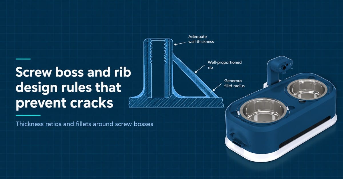
Boss and Rib Design Rules That Prevent Cracks
Screw bosses crack when the boss wall is too thick, the base corner is sharp, or the screw splits an over-stressed wall. A rib base of 0.5 times the wall, a boss wall of 0.6 times the wall and a base fillet of 0.4 times the wall cut our boss cracks from 7.1 percent to 0.8 percent of 240 bosses.
This post covers why bosses and ribs crack, the thickness ratios and fillet radii we use, the two numbers we track, and what stable screw mounts let EverBowl do.
Boss and rib rules at a glance
- A rib base of 0.5 times the nominal wall (1.5 mm on a 3.0 mm wall) avoids the hot spot that leads to sink and voids.
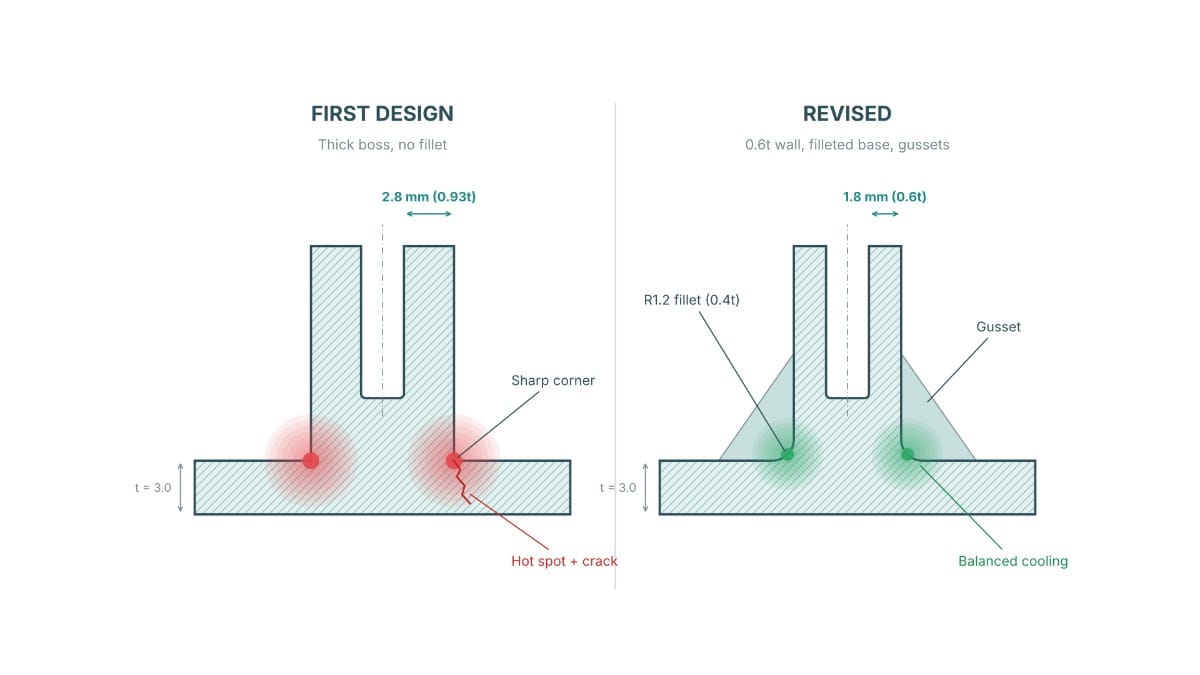
- A boss wall of 0.6 times the wall (1.8 mm) with a base fillet of 0.4 times the wall (1.2 mm) removed the sharp corner where 13 of our 17 first-generation cracks began.
- The first design cracked 17 of 240 bosses (7.1 percent), and the revised rules cracked 2 of 240 (0.8 percent).
- A strip torque of at least 3 times the driving torque keeps the screw from splitting the boss.
What cracked first
Our first housing had a 3.0 mm nominal wall and M3 screws. We made the bosses 8.0 mm in diameter because thick felt strong. That left a boss wall of 2.8 mm, almost the full wall, with ribs at 2.4 mm and only a 0.3 mm radius at the base.
We tested 40 housings with 6 bosses each, 240 bosses in total. Each screw was driven and removed 5 times, then the housing sat in a diluted detergent soak for 24 hours with the screws torqued. 17 bosses cracked: 13 started as a hairline ring at the base corner, and 4 split radially from the bore.
Most cracks appeared after the soak, not after assembly. That pointed to locked-in stress plus chemical attack, not screw load alone. Cleaners and oils hit amorphous resins such as ABS and PC blends hardest where tensile stress is already high.
Why the base corner cracks
The boss carries the screw load like a cantilever, so the base corner sees the highest bending stress. A sharp inside corner multiplies that local stress. Handbook curves for plastic steps put the multiplier near 3 at a sharp corner, about 2 at a radius of 0.25 times the wall, and about 1.5 at 0.5 times the wall.
More radius is not always better. Past 0.5 times the wall, the fillet adds mass at the junction and brings the hot spot back. The working band is 0.25 to 0.5 times the wall, and we use 0.4.
Why thick junctions sink and void
Cooling time in a molded part grows with the square of thickness. A junction 1.5 times the nominal wall cools about 2.25 times slower. That hot spot freezes last, shrinks last, and either pulls the skin inward as a sink mark or tears open as an internal void.
A void is a crack seed, and the skin around it holds residual tensile stress. By our estimate, the first design had junctions near 1.5 times the wall. The revised design sits near 1.2 times, about 1.44 times slower than the wall.
Engineering insight: The sink mark on the outside face is only the warning. The void and the residual stress under it are the real problem.
Why the screw splits the wall
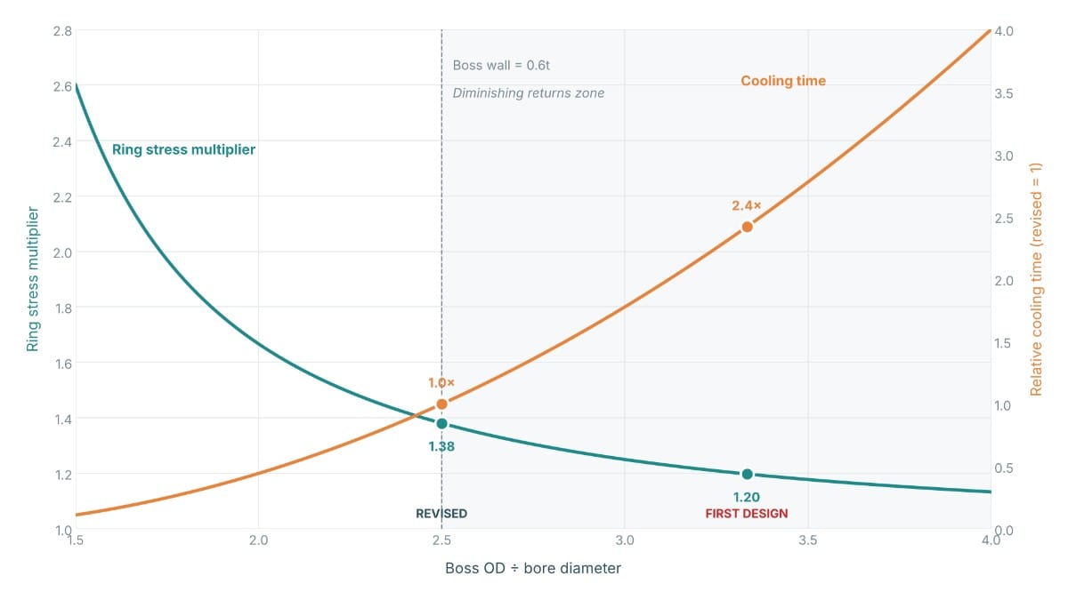
A thread-forming screw pushes plastic outward as it cuts its thread. The boss wall behaves like a thick-walled cylinder under internal pressure. Ring (hoop) stress at the bore is the pressure times (ro² + ri²) ÷ (ro² − ri²), where ro is the boss outer radius and ri is the bore radius.
With a 2.4 mm bore, the revised boss (6.0 mm outer diameter, ratio 2.5) gives a multiplier of 1.38. The thick first boss (8.0 mm, ratio 3.3) gives 1.20. A wall 56 percent thicker bought only 13 percent lower ring stress, and it cost us the hot spot.
Engineering insight: Extra boss wall has diminishing returns for ring stress and increasing penalties for cooling. A boss wall of 0.6 times the nominal wall is the knee of that curve.
Rib rules
Ribs add stiffness without adding wall. They also create the junction we just covered, so their thickness matters more than their height.
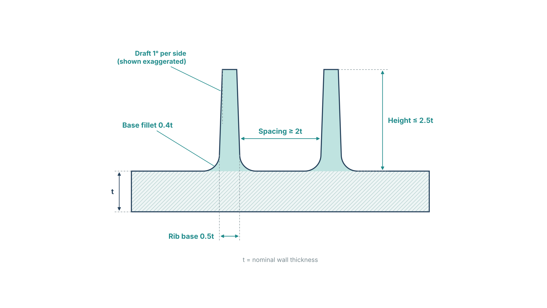
Step 1: Set the base thickness at 0.5 times the wall
The usable range is 0.4 to 0.6 times the wall, depending on resin. On a 3.0 mm wall, that is 1.5 mm. As a rule of thumb, stay at or below 50 percent behind a textured face and near 30 percent behind a glossy one.
Step 2: Cap the height at 3 times the wall
Tall ribs are hard to fill and hard to eject. We cap ours at 2.5 times the wall, which is 7.5 mm. Two short ribs stiffen better than one tall rib, and the first design had a 12 mm rib.
Step 3: Add draft and spacing
Use 1 degree of draft per side, inside the typical 0.5 to 1.5 degree range. Keep parallel ribs at least 2 times the wall apart, which is 6 mm here, or the thin steel between them in the mold overheats. Align each rib with the bending load, or it adds no stiffness.
Boss rules
Step 1: Size the hole at 0.8 times the screw diameter
That is 2.4 mm for an M3 thread-forming screw. A smaller hole raises ring stress, and a larger hole lowers pull-out strength.
Step 2: Set the boss diameter near 2 times the screw diameter
A 6.0 mm outer diameter gives a 1.8 mm boss wall, which is 0.6 times the nominal wall. Keep boss height under 3 times the outer diameter so the core pin can cool. Plan thread engagement of at least 2.5 times the screw diameter (7.5 mm), plus 1 mm of relief at the hole bottom.
Step 3: Tie the boss to the wall with gussets
A free-standing boss is a lever. We use three gussets at 120 degrees, each 1.5 mm thick (0.5 times the wall) and about 6 mm tall (2 times the wall). Never bury a boss in a corner where two walls meet, because that builds a thick mass. Isolate it.
Step 4: Fillet the base and the hole
The base fillet is 1.2 mm (0.4 times the wall). The hole bottom gets a 0.25 mm radius so the core pin leaves no sharp corner.
Step 5: Set a torque margin
We drive M3 screws at 0.4 N·m and want a strip torque of at least 1.2 N·m, a ratio of 3. The first design stripped at 0.8 N·m, a ratio of 2.0. The revised design stripped at 1.4 N·m, a ratio of 3.5.
Any screw a technician will remove more than 5 times gets a brass heat-set insert, not a thread-forming screw.
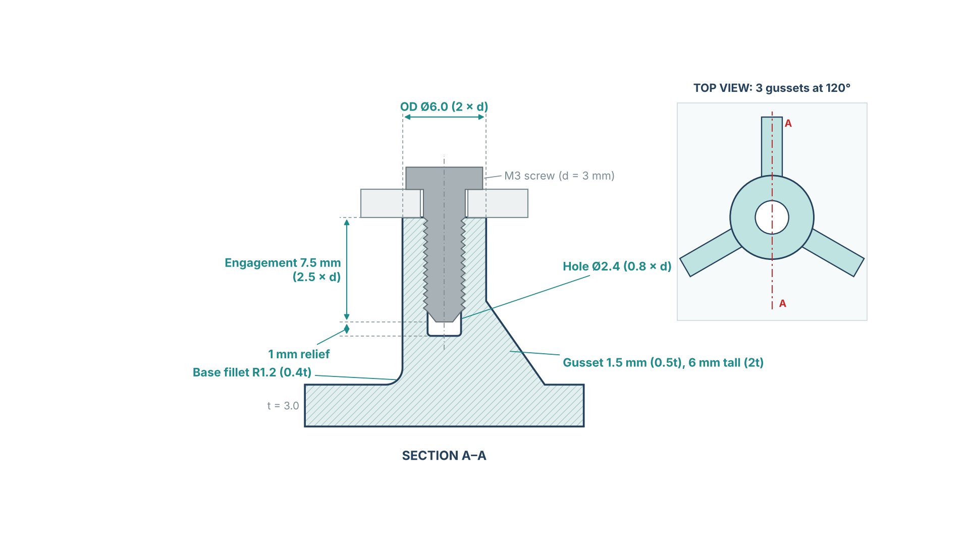
Stage by stage
| Feature | First design | Revised rule |
|---|---|---|
| Rib base thickness | 2.4 mm (0.8t) | 1.5 mm (0.5t) |
| Rib height | 12 mm (4t) | 7.5 mm (2.5t) |
| Rib draft | 0.25 degrees | 1 degree |
| Boss wall | 2.8 mm (0.93t) | 1.8 mm (0.6t) |
| Base fillet | 0.3 mm (0.1t) | 1.2 mm (0.4t) |
| Strip to drive torque | 2.0 | 3.5 |
| Boss crack incident rate | 7.1% | 0.8% |
The 2 cracks left in the revised lot both traced to one driver set above 0.6 N·m. That is a process fix, not a geometry fix.
Two numbers we track
Rib-to-Wall Ratio
Rib-to-Wall Ratio = Rib base thickness ÷ Nominal wall thickness
We hold it between 0.4 and 0.6 and aim for 0.5.
Boss Crack Incident Rate
Boss Crack Incident Rate (%) = (Bosses with cracks ÷ Bosses tested) × 100
We wipe each boss with dye and inspect it at 10x after the assembly cycles and again after the detergent soak. Both numbers are logged for every housing revision.
Why this matters for EverBowl
EverBowl™ learns to recognize which pet is at the bowl, and that depends on a camera that stays where we aimed it. The camera mount and board stack sit on screw bosses. A cracked boss lets the mount shift, and the dog’s head drifts out of frame, as we covered in our post on camera height and field of view.
Stable bosses keep the framing steady through months of washing, so recognition gets cleaner frames and the record stays consistent. The honest limit is that these rules are validated on our prototype housings and bench tests, not yet on years in homes. The honest limit is that these rules are validated on our prototype housings…
Conclusion
Set the rib base at 0.5 times the wall, the boss wall at 0.6 times, the fillets at 0.4 times, and the torque margin at 3. Check every housing revision against these ratios before tooling is cut. Run the 5-cycle and detergent soak test on the first lot and log the crack rate. Fix sharp corners first, because they are the cheapest change.
More of our mechanical design work is in the product category page for this series.
FAQs
1.What rib thickness prevents sink marks?
Keep the rib base at 40 to 60 percent of the nominal wall, and about 50 percent behind a textured face. Thicker ribs create a hot spot that shrinks last and pulls the outer skin inward.
2.How thick should a screw boss wall be?
Keep it under 60 percent of the nominal wall at the base. On a 3.0 mm wall, that means about 1.8 mm. A thicker wall barely lowers ring stress but slows cooling and invites voids.
3.What fillet radius should go at the base of a boss?
Use 0.25 to 0.5 times the nominal wall. We use 0.4 times, which is 1.2 mm on a 3.0 mm wall. Larger radii add mass and bring back the hot spot.
4.Why do bosses crack after washing?
Molding leaves residual tensile stress near the boss base. Detergents and oils attack amorphous resins at those stressed spots, so a hairline can open days after assembly. Fillets and thinner walls lower that stress.
5.Should I use thread-forming screws or inserts in plastic?
Use thread-forming screws for fasteners that are installed once. Use heat-set inserts for any screw a technician will remove many times, because repeated thread forming wears the boss and loosens the joint.